
Views: 0 Author: Site Editor Publish Time: 2026-10-21 Origin: Site


Unverified dimensional variances in raw or machined forgings cause severe downstream assembly failures. They increase secondary machining scrap rates dramatically. These inconsistencies ultimately compromise your machinery's lifecycle. You cannot risk these operational disruptions. Our core objective is to establish a standardized, evidence-based dimensional inspection framework. This framework evaluates supplier quality and minimizes your daily operational risk. We will clearly bridge the critical gap between raw as-forged tolerances and the precise requirements of finished parts. You will discover exactly which features demand rigorous validation. We cover everything from initial die mismatch limits to advanced surface finish profiling. Understanding these geometric checks prevents costly production delays. This guide equips you to hold manufacturing partners accountable at every stage.
As-forged inspection must prioritize die mismatch, thickness tolerances, and straightness to account for thermal distortion and tooling wear.
Transitioning to CNC machined steel forgings requires verifying datum references, concentricity, and mating surface finishes.
Reliable inspection protocols blend automated CMM verification with Statistical Process Control (SPC) to track dimensional drift over production runs.
Evaluating a supplier’s quality control maturity is a critical risk mitigation step before sourcing custom forged components.
Dimensional variance creates hidden financial drains across your production floor. When raw components arrive out of tolerance, your secondary machining processes suffer. Oversized parts force CNC spindles to work harder. This excessive material removal accelerates tool wear drastically. Cycle times inflate because operators must reduce their cutting feeds and speeds. Conversely, undersized parts leave no material for cleanup passes. You end up scrapping these parts immediately. Poor quality directly inflates your manufacturing overhead and delays shipment schedules.
You must distinguish between acceptable dimensional deviations and critical geometric failures. A minor surface blemish on a non-mating face rarely affects product function. It represents an acceptable deviation. However, a slight angular deviation on a mounting flange prevents assembly. This is a critical fit failure. Your inspection criteria must prioritize features that dictate how the component interacts with other sub-assemblies. Focusing heavily on critical fit characteristics streamlines your quality control process.
Preventing systemic batch rejections requires proactive validation. Robust First Article Inspection (FAI) provides the initial safeguard. FAI verifies that the forging dies and machining fixtures produce correct geometry under production conditions. However, FAI alone is insufficient. You must implement routine dimensional sampling throughout the production run. This continuous sampling catches tool wear and thermal drift early. It prevents a single tooling error from ruining an entire shipment of Steel Forgings.
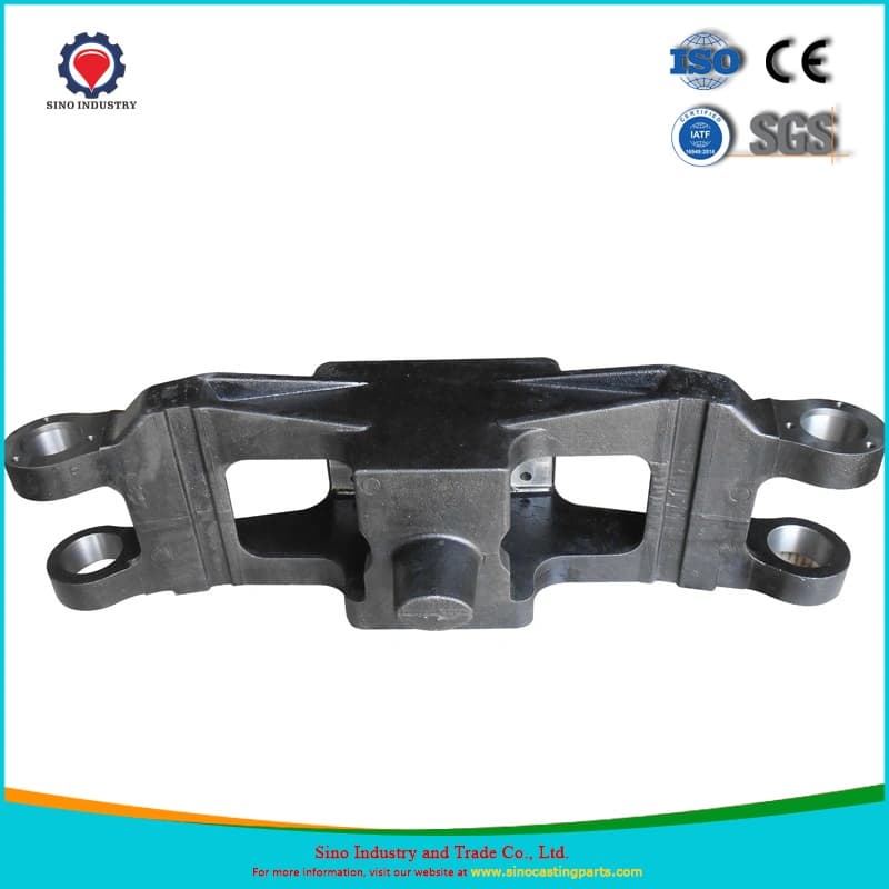
Die mismatch occurs when the upper and lower forging dies misalign during the pressing cycle. This lateral shift fundamentally alters the part's cross-section. Inspecting this alignment is absolutely crucial. A severe mismatch reduces your machining allowance on one side of the part. It simultaneously leaves excessive stock on the opposite side. This imbalance leads to incomplete clean-up during machining and unbalanced cutting forces.
Press tonnage and temperature variations affect how fully the dies close. If the dies do not close completely, the resulting part will be too thick. Furthermore, die cavities experience severe abrasion over high-volume production runs. This tooling wear causes the forged parts to gradually grow in length and width. You must monitor thickness and length tolerances consistently to detect die wear early.
Forged parts endure extreme thermal cycles. Uneven cooling rates introduce residual stresses into the metal structure. Aggressive heat treatment processes, such as quenching, exacerbate these stresses. This thermal distortion typically manifests as warpage in long shafts or bowing in flat plates. Evaluating straightness and flatness ensures the part will fit securely into its first machining fixture without rocking or bowing.
Excess metal squeezes out between the dies during forging, creating flash. Secondary trimming presses shear this flash away. Trimming operations demand strict tolerance checks. If the trim die shifts, it may undercut the structural body of the part. Alternatively, it might leave excessive jagged material behind. Excessive flash extension disrupts the precise clamping forces needed during automated machining processes.
Draft angles allow the hot metal part to eject smoothly from the die cavity. Fillet radii prevent stress concentrations at sharp corners. Ensuring compliance with these Design for Manufacturing (DFM) requirements is vital. Incorrect draft angles cause parts to stick, damaging the component during ejection. Inadequate radii create internal structural stress points that lead to premature fatigue failures in the field.
Geometric Feature | Primary Inspection Method | Common Defect Risk |
|---|---|---|
Die Mismatch | Caliper across parting line | Uneven machining allowance |
Thickness Variation | Micrometer / Hard Gauge | Die closure failure |
Straightness | Dial indicator on V-blocks | Thermal warpage from quenching |
Trim Tolerance | Visual comparison / Go-No-Go | Clamping fixture interference |
The transition from a raw forging to a finished component relies heavily on accurate datums. Initial machining cuts establish the primary, secondary, and tertiary datums. These baseline planes dictate the accuracy of all subsequent tight-tolerance operations. If the initial datum face is machined at a slight angle, every subsequent hole, pocket, and thread will be misaligned. Verifying these primary datums is the most critical step in precision machining.
Rotational components demand strict concentricity checks. Gear blanks, drive shafts, and bearing housings must spin seamlessly. Runout measures how much a rotating part wobbles on its axis. High runout generates severe vibration during operation. This vibration destroys adjacent seals and causes premature bearing failure. You must utilize specialized inspection setups to guarantee concentricity across all cylindrical features.
Precision machinery requires parts that integrate flawlessly. You must meticulously inspect bore diameters, keyways, and critical contact faces. A keyway machined just slightly too wide causes backlash in a transmission system. A bearing bore machined too tight prevents assembly entirely. When evaluating CNC machined steel forgings for machinery, these mating surfaces often carry micron-level tolerances that dictate operational success.
Dimensional accuracy alone does not guarantee a successful part. Surface finish directly impacts component performance. Rough surfaces increase mechanical friction and accelerate wear between sliding parts. They also provide poor sealing surfaces, leading to hydraulic fluid leaks. Validating the surface roughness (measured in Ra) ensures the component meets strict friction and fluid containment requirements.
Verify primary machining datums against the engineering drawing.
Measure total indicator runout (TIR) on all rotational bearing journals.
Confirm internal bore diameters using specialized three-point micrometers.
Validate surface roughness on all dynamic sealing faces.
Check angularity and perpendicularity of all mounting flanges.
Modern quality control relies heavily on Coordinate Measuring Machines. CMMs utilize programmable tactile probes to touch specific points on a part. They calculate complex geometric dimensioning and tolerancing (GD&T) profiles with extreme precision. Advanced CMMs also feature optical heads for non-contact measurements. These machines eliminate human error from the inspection process. They provide an undisputed, objective validation of your most critical geometries.
Speed is essential during high-volume production. Optical scanning uses non-destructive lasers to capture millions of surface data points in seconds. Inspection software overlays this digital point cloud directly onto the original CAD model. It instantly highlights dimensional deviations using a color-coded heat map. This 3D profiling technique allows quality engineers to verify entire batches rapidly without bottlenecking production flow.
While digital tools are powerful, traditional hard gauging remains indispensable. Go/No-Go gauges, micrometers, and vernier calipers facilitate localized checks directly on the shop floor. Machine operators use these tools to verify features immediately after a cutting cycle finishes. This instant feedback loop prevents defective parts from moving downstream. Hard gauging provides a practical, robust line of defense against sudden dimensional shifts.
Inspection data is only valuable if you analyze it properly. Statistical Process Control utilizes control charts to track dimensional trends over time. As cutting tools wear down, the dimensions of CNC machined steel forgings gradually drift toward the tolerance limits. SPC highlights this drift before the parts actually fail inspection. It enables proactive tool changes and stabilizes your entire manufacturing capability.
Tool Category | Primary Application | Speed | Accuracy Level |
|---|---|---|---|
Tactile CMM | Complex GD&T, internal bores, exact datums | Slow | Extremely High |
Laser 3D Scanner | Full surface profiling, rapid batch checks | Very Fast | High |
Go/No-Go Gauges | In-process shop floor validation | Instant | Pass/Fail Only |
Micrometers | Precise thickness and outer diameter checks | Fast | Very High |
A supplier’s internal systems dictate their product reliability. You must require baseline quality certifications before placing an order. Certifications like ISO 9001 or AS9100 demonstrate a structured approach to manufacturing control. You should look for transparent, traceable documentation practices. A certified supplier manages raw material lots carefully and prevents cross-contamination. These systems form the foundation of consistent dimensional accuracy.
The best suppliers do not just follow drawings blindly. They actively engage in Design for Manufacturing collaboration. Assess a manufacturer's ability to predict geometric challenges during the initial tooling design phase. Can they suggest minor geometry changes to prevent thermal warpage? Do they recommend larger draft angles to improve die life? Proactive collaboration mitigates dimensional risks before any metal is heated.
When sourcing custom steel forgings, you cannot rely on blind trust. Transparent reporting is an absolute necessity. Demand comprehensive material test reports (MTRs) to verify chemical composition and yield strength. Furthermore, dimensional inspection logs must accompany every single shipment. These logs prove that the supplier actually measured the parts against the agreed-upon sampling plan.
Take proactive steps to audit a prospective supplier’s internal inspection facility. Look closely at their environmental controls; CMM rooms must be temperature-regulated to ensure accuracy. Review their calibration logs to confirm their hard gauges are checked regularly against master blocks. Scrutinize their inspection sampling frequency. A mature supplier will proudly demonstrate how they tie their SPC data directly to their tooling maintenance schedules.
Consistent dimensional accuracy separates high-performing structural components from costly liabilities. Failing to inspect raw die mismatch or finished runout guarantees downstream assembly failure. Implementing a structured blend of CMM validation, on-floor hard gauging, and continuous SPC tracking eliminates these risks entirely.
Buyers must proactively demand transparent, well-documented dimensional inspection protocols from their manufacturing partners. Do not accept assumed tolerances. Define your critical fit characteristics clearly, and enforce routine sampling to monitor tool wear before it compromises your batch.
Submit your part drawing for a comprehensive DFM and tolerance capability review today. Aligning your engineering specifications with proven manufacturing capabilities ensures seamless production and long-term quality integration.
A: Dimensional checks should begin with a comprehensive First Article Inspection (FAI) to validate the setup. Once production starts, perform periodic sampling based on defined Statistical Process Control (SPC) limits. Operators should conduct hourly localized gauge checks, followed by a final randomized lot inspection before shipment.
A: Standard commercial forging tolerances usually range from ±0.030 to ±0.125 inches, depending heavily on part size and weight. Precision closed-die forging can achieve tighter tolerances. Buyers should always reference standard guidelines like EN 10243 or ASME standards to align expectations with manufacturing capabilities.
A: Asymmetric geometries and extreme thickness variations cool at dramatically different rates. This uneven cooling creates internal residual stresses, increasing the risk of severe thermal distortion or warpage. Complex configurations dictate much stricter inspection requirements and often require specialized heat treatment fixtures to maintain straightness.
A: CNC machining refines specific features but cannot salvage fundamental forging defects. If a raw forging suffers from severe die mismatch or lacks adequate machining allowance, the cutting tools will not have enough material to establish critical datums. Gross dimensional errors in the raw state guarantee scrap.


